
ESP8266 Pinout
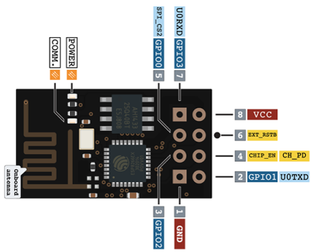
ESP8266-01
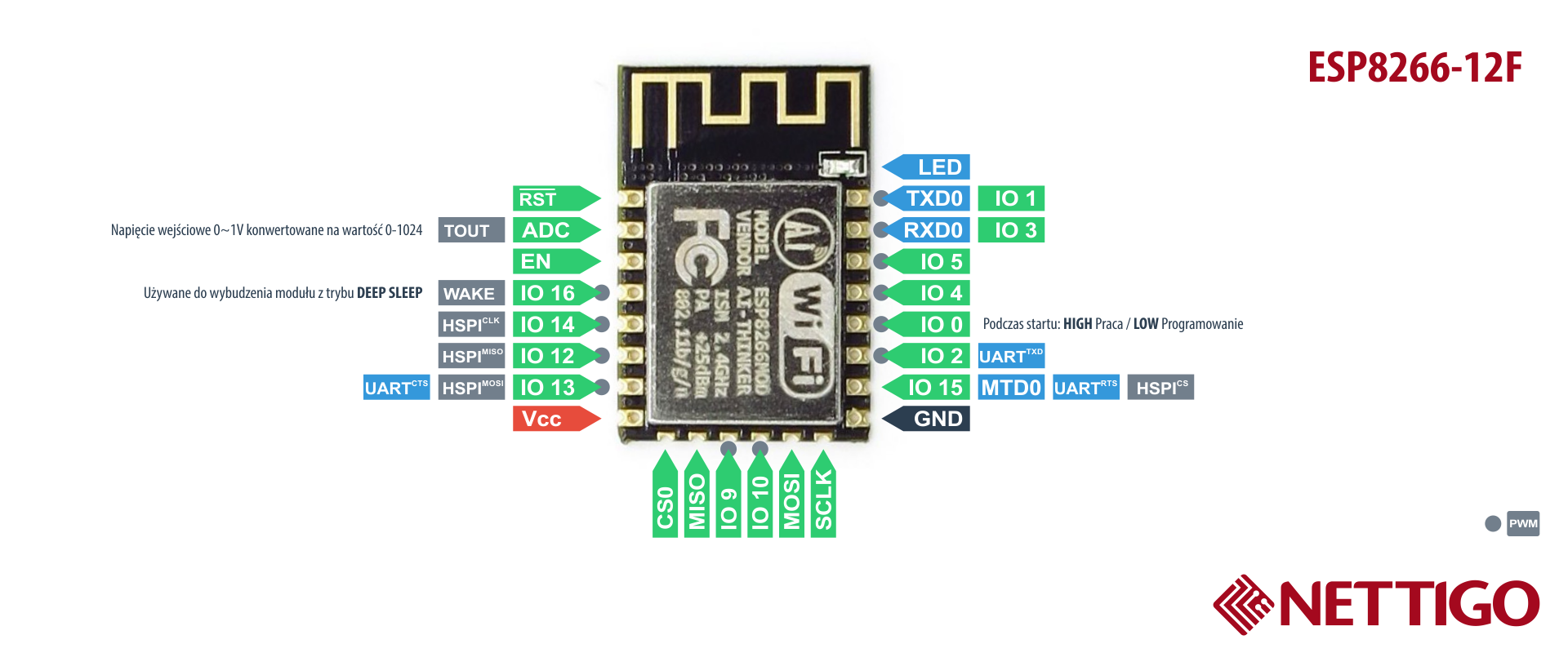
ESP8266-12F
| Label | GPIO | Input | Output | Notes |
|---|---|---|---|---|
| D0 | GPIO16 | no interrupt | no PWM or I2C support | HIGH at boot, used to wake up from deep sleep |
| D1 | GPIO5 | OK | OK | often used as SCL (I2C) |
| D2 | GPIO4 | OK | OK | often used as SDA (I2C) |
| D3 | GPIO0 | pulled up | OK | connected to FLASH button, boot fails if pulled LOW |
| D4 | GPIO2 | pulled up | OK | HIGH at boot connected to on-board LED, boot fails if pulled LOW |
| D5 | GPIO14 | OK | OK | SPI (SCLK) |
| D6 | GPIO12 | OK | OK | SPI (MISO) |
| D7 | GPIO13 | OK | OK | SPI (MOSI) |
| D8 | GPIO15 | pulled to GND | OK | SPI (CS), Boot fails if pulled HIGH |
| RX | GPIO3 | OK | RX pin | HIGH at boot |
| TX | GPIO1 | TX pin | OK | HIGH at boot, debug output at boot, boot fails if pulled LOW |
| A0 | ADC0 | Analog | Input | X |
Pins used during Boot
- GPIO16: pin is high at BOOT
- GPIO0: boot failure if pulled LOW
- GPIO2: pin is high on BOOT, boot failure if pulled LOW
- GPIO15: boot failure if pulled HIGH
- GPIO3: pin is high at BOOT
- GPIO1: pin is high at BOOT, boot failure if pulled LOW
- GPIO10: pin is high at BOOT
- GPIO9: pin is high at BOOT
Analog Input
The maximum input voltage of the ADC0 pin is 0 to 1V if you’re using the ESP8266 bare chip. If you’re using a development board like the ESP8266 12-E NodeMCU kit, the voltage input range is 0 to 3.3V because these boards contain an internal voltage divider.
RST Pin
When the RST pin is pulled LOW, the ESP8266 resets. This is the same as pressing the on-board RESET button.
GPIO0
When GPIO0 is pulled LOW, it sets the ESP8266 into bootloader mode. This is the same as pressing the on-board FLASH/BOOT button.
GPIO16
GPIO16 can be used to wake up the ESP8266 from deep sleep. To wake up the ESP8266 from deep sleep, GPIO16 should be connected to the RST pin.
I2C
The ESP8266 doens’t have hardware I2C pins, but it can be implemented in software. So you can use any GPIOs as I2C. Usually, the following GPIOs are used as I2C pins:
- GPIO5: SCL
- GPIO4: SDA
SPI
The pins used as SPI in the ESP8266 are:
- GPIO12: MISO
- GPIO13: MOSI
- GPIO14: SCLK
- GPIO15: CS
PWM Pins
ESP8266 allows software PWM in all I/O pins: GPIO0 to GPIO15. PWM signals on ESP8266 have 10-bit resolution.
Interrupt Pins
The ESP8266 supports interrupts in any GPIO, except GPIO16.